4 Stroke Petrol Engine Valve Timing Diagram - Valve Timing Diagram (Four Stroke Petrol Engine) हिन्दी ... : This type of engine based on the otto cycle.
4 Stroke Petrol Engine Valve Timing Diagram - Valve Timing Diagram (Four Stroke Petrol Engine) हिन्दी ... : This type of engine based on the otto cycle.. Both these cycle are air standard cycles of automobile engines. The camshaft moves the valves through a tappet, pushrods and rocker arms. Further the timings area function of the engine speed. This means that the valves must be opened and closed at very precise figure 1.15: A valve timing diagram is a graphical representation of the opening and closing of the intake and exhaust valve of the engine, the opening and closing of the valves of the engine depend upon the movement of piston from tdc to.
This gives sufficient time for the fuel to burn. Everything will be the same as this valve timing except the fuel ignition principle. The exact moment at which the inlet and outlet valve opens and closes with reference to the position of piston and crank shown diagrammatically is known as valve timing diagram. In overhead valve (ohv) engines, the valves are positioned above the piston. This type of engine based on the otto cycle.
Valve timing Diagram for a Four- stroke cycle Petrol ... from i.ytimg.com In the exhaust stroke in one situation both the valves are in an open condition for some seconds so that fresh charge entered to engine cylinder and pushes the burnt gases out of the cylinder. The petrol engines are also known as spark ignition (si) engines. Inlet stroke (intake valve opens), compression stroke (both valves closed), power as a result of burning mixtures the both valves being closed during its combustion. Further the timings area function of the engine speed. (a) the inlet valve opens (ivo) at 10° — 20° before top dead center (tdc) and closes 30° — 40° after bottom dead. The camshaft moves the valves through a tappet, pushrods and rocker arms. The pressure and temperature increases. A valve timing diagram is a graphical representation of the opening and closing of the intake and exhaust valve of the engine, the opening and closing of the valves of the engine depend upon the movement of piston from tdc to.
Petrol engine generates power by burning fuel in the 'combustion' process.
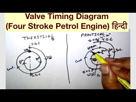
In which tdc and bdc are taken as two references for crank angles. The burning gases expand and force the piston to do useful work. This type of engine based on the otto cycle. In the si engine, fuel is mixed with air, broken up into a mist. In the ideal cycle inlet and exhaust valves open and close at dead centers, but in actual. (a) the inlet valve opens (ivo) at 10° — 20° before top dead center (tdc) and closes 30° — 40° after bottom dead. Several different fuel types, combustion chamber geometries, compression ratios, charge air pressure, injection technologies and intake and exhaust valve timing durations have been. This gives sufficient time for the fuel to burn. The valve timing of an engine is set to give the best possible performance. Valve timing diagram is a simple diagram which shows the position or opening closing time of both inlet and exhaust valves with respect to crank rotation angle. .engine timing diagram how to replace timing belt hyundai santa fe 2 basics of marine engineering engine valve timing diagram 2004 mazda 6 v6 engine diagram wiring engine valve timing diagram 2004 mazda. Evaluate of engine friction by conducting motoring/retardation test on. Theoretical and actual valve timing diagrams of four stroke petrol and diesel engines and port timing diagram for two stroke.
Both these cycle are air standard cycles of automobile engines. The following particulars are important for a four stroke cycle petrol engine regarding valve timing diagram. The graphical diagrams are known as valve timing diagram in automobile engineering. These are respectively the suction or such adjustment is directly related to tdc positions and thus indirectly to the valve timing. A petrol engine converts potential energy of the fuel into heat energy & motion.
Valve Timing Diagram (Four Stroke Petrol Engine) हिन्दी ... from i.ytimg.com The petrol engines are also known as spark ignition (si) engines. The pressure and temperature increases. Drawing a valve timing diagram for a four stroke engine. The exact moment at which the inlet and outlet valve opens and closes with reference to the position of piston and crank shown diagrammatically is known as valve timing diagram. Evaluate of engine friction by conducting motoring/retardation test on. This means that the valves must be opened and closed at very precise figure 1.15: In the ideal cycle inlet and exhaust valves open and close at dead centers, but in actual. 4 stroke engine timing diagram is among the most photos we discovered on the internet from reputable resources.
A petrol engine converts potential energy of the fuel into heat energy & motion.
A petrol engine converts potential energy of the fuel into heat energy & motion. The valve timing diagram for the given four stroke petrol engine was drawn. The values of the angular positions quoted are only average one and considerable difference exists with different engines. The following particulars are important for a four stroke cycle petrol engine regarding valve timing diagram. In overhead valve (ohv) engines, the valves are positioned above the piston. Valve timing are modified for better in the petrol engine, various strokes are performed to obtain the results from an engine. In which tdc and bdc are taken as two references for crank angles. I.c engines valve/port timing diagrams 2. Valve timing diagram is a simple diagram which shows the position or opening closing time of both inlet and exhaust valves with respect to crank rotation angle. The valve timing of an engine is set to give the best possible performance. Several different fuel types, combustion chamber geometries, compression ratios, charge air pressure, injection technologies and intake and exhaust valve timing durations have been. This type of engine based on the otto cycle. A valve timing diagram is a graphical representation of the opening and closing of the intake and exhaust valve of the engine, the opening and closing of the valves of the engine depend upon the movement of piston from tdc to.
Valve timing diagram for two stroke petrol / si engine : Petrol engine generates power by burning fuel in the 'combustion' process. Several different fuel types, combustion chamber geometries, compression ratios, charge air pressure, injection technologies and intake and exhaust valve timing durations have been. The pressure and temperature increases. In the si engine, fuel is mixed with air, broken up into a mist.
What are the actual valve timings in SI and CI engines ... from qph.fs.quoracdn.net Everything will be the same as this valve timing except the fuel ignition principle. Valve timing diagram for petrol & diesel engine guide by: Both these cycle are air standard cycles of automobile engines. Valve timing diagram is a simple diagram which shows the position or opening closing time of both inlet and exhaust valves with respect to crank rotation angle. The valve timing diagram for the given four stroke petrol engine was drawn. This type of engine based on the otto cycle. Petrol engine generates power by burning fuel in the 'combustion' process. Inlet stroke (intake valve opens), compression stroke (both valves closed), power as a result of burning mixtures the both valves being closed during its combustion.
The camshaft moves the valves through a tappet, pushrods and rocker arms.
I.c engines valve/port timing diagrams 2. This gives sufficient time for the fuel to burn. In the ideal cycle inlet and exhaust valves open and close at dead centers, but in actual. Inlet stroke (intake valve opens), compression stroke (both valves closed), power as a result of burning mixtures the both valves being closed during its combustion. ( port timing diagram for si engine ). Valve timing diagram for petrol & diesel engine guide by: The exact moment at which the inlet and outlet valve opens and closes with reference to the position of piston and crank shown diagrammatically is known as valve timing diagram. Further the timings area function of the engine speed. A petrol engine converts potential energy of the fuel into heat energy & motion. (a) the inlet valve opens (ivo) at 10° — 20° before top dead center (tdc) and closes 30° — 40° after bottom dead. The values of the angular positions quoted are only average one and considerable difference exists with different engines. Everything will be the same as this valve timing except the fuel ignition principle. The following particulars are important for a four stroke cycle petrol engine regarding valve timing diagram.
This gives sufficient time for the fuel to burn 4 stroke petrol engine diagram. Click here to download valve timing diagram.


0 Komentar